A flat pattern can be ready for cutting while the brake paperwork still needs work. Someone has to identify the bends, choose a useful dimension convention, put the bends in an understandable order, and carry the setup information onto a sheet.
Brake Card is Doubler Aerospace’s prototype for that handoff: flat DXF in, bend dimensions and a press sheet out. This engineering note explains the implementation, where human review remains necessary, and a small working code example you can inspect. It is a development case study, not a report of measured production savings.
1. Automate the repeated drawing work
The prototype reads DXF geometry in the browser, separates cut paths from bend and tangent lines using layer conventions, and builds an SVG drawing sheet. The interface supports batches of up to ten drawings. A designer can enter thickness, revision, punch and die identifiers, remarks, first-bend orientation, finger count and people count.
The drawing combines the flat, dimension callouts and a bend table. The implementation offers printing and SVG, PNG and JPEG export. SVG retains vector geometry; PNG and JPEG are raster images. An optional formed-part photograph can provide visual context. That photograph is uploaded by the user—the tool does not generate a formed 3D view.
The intended benefit is a more consistent handoff: the geometry and table come from the same model, so labels can follow sequence edits. Before claiming time savings, a shop would need to compare representative jobs against its existing method and record preparation time, corrections and first-piece results.
2. Name the reference behind every dimension
“Distance to the bend” is ambiguous. Is the start point a cut edge, the previous bend center, or a tangent boundary? Brake Card keeps two choices separate:
| Mode | Chain | Interpretation |
|---|---|---|
| Measure bend to bend | Edge → center; center → center; center → far edge | A geometric chain across a parallel bend family. For a single bend, the shorter flange is shown. |
| Tangent to center | Edge → first center; previous bend’s incoming tangent → next center | Uses the first tangent encountered when approaching the previous bend. It is not a center-to-center distance. |
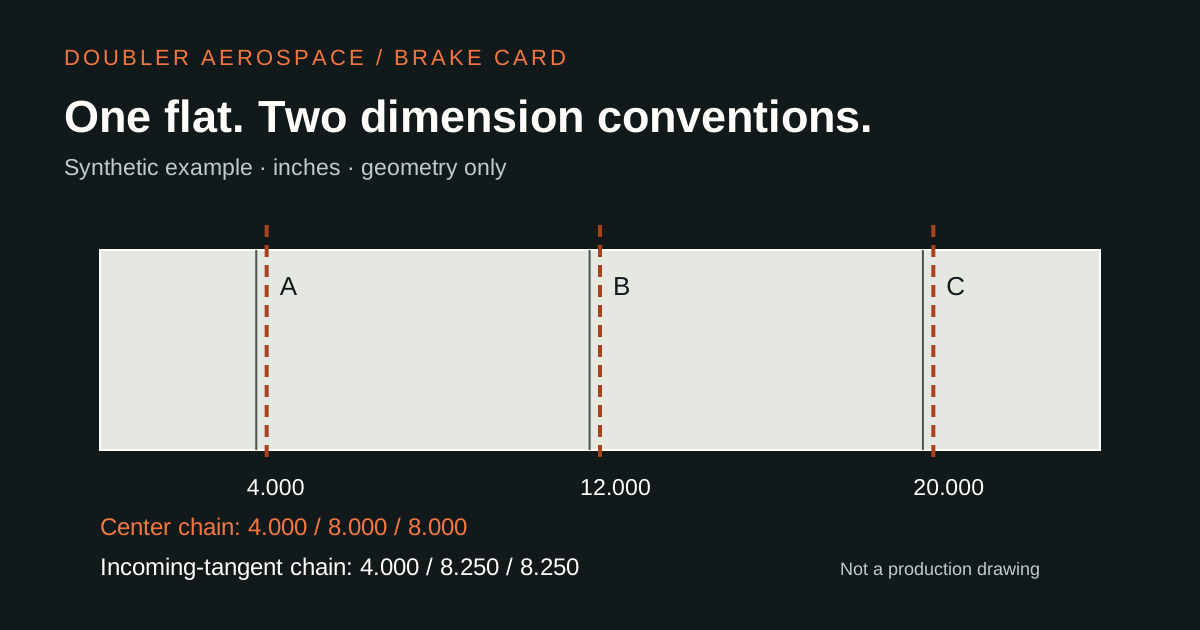
Consider a synthetic blank with centers at 4, 12 and 20 inches. Place each incoming tangent 0.25 inches before its center: 3.75, 11.75 and 19.75. The first dimension is 4.000 inches in either mode. The next center-to-center distance is 12 − 4 = 8.000 inches. The corresponding tangent-to-center distance is 12 − 3.75 = 8.250 inches. That 0.250-inch difference comes entirely from the reference choice.
The full geometry routine groups approximately parallel lines into families using a 15° tolerance. In the tangent routine, successive lines separated by less than 0.85 inches can join a bend zone; nearby parallel tangent-layer lines can extend it within a 0.9-inch threshold. These are implementation heuristics, not fabrication tolerances. Closely spaced bends or unusual layer exports can therefore need correction.
The routine starts from the end closer to the bend group and looks for suitable overlapping cut geometry. If it cannot identify a clean edge, it can fall back to the bounding box. A long rail with a bend near one end illustrates why this matters: a short local reference may be easier to interpret than a dimension across almost the whole rail. The operator still has to confirm the usable gauging surface and tooling setup.
3. A small, runnable dimension example
The example below isolates the arithmetic after bend centers and tangents have already been identified. It accepts increasing coordinates in inches from a reviewed starting edge. It does not parse DXF, choose an edge, detect bend families, add the final far-edge segment, or compute a machine backgauge position.
Download the JavaScript module · Download the tests
import { dimensionChain } from './bend-dimensions.mjs';

const rows = dimensionChain({
  centers: [4, 12, 20],
  tangents: [3.75, 11.75, 19.75],
  mode: 'tangent'
});
console.log(rows.map(row => row.inches));
// [4, 8.25, 8.25]
The important selection is small enough to inspect:
const from = i === 0 ? edge
  : mode === 'center' ? centers[i - 1]
  : tangents[i - 1];
const distance = centers[i] - from;
The downloadable module adds finite-number checks, strictly increasing centers and tangent bounds. Its tests cover the hand-calculated example, translation invariance, a single bend, and malformed coordinates. Save both downloaded files in the same folder. With Node.js installed, run node --test bend-dimensions.test.mjs. The example import above uses the downloaded module directly.
4. Keep sequence, angles and geometry separate
The prototype provides an initial geometric order and lets the user move bends up or down. Letters on the flat and rows in the table follow that edit. The dimension chain remains tied to geometry rather than being recomputed as though the operator’s sequence were a new coordinate system. That separation keeps a sequence change from silently changing what a dimension means.
For angles, an explicitly typed per-bend value takes priority over the global setup value; the global value takes priority over a value carried by the model. The setup parser rejects blank, non-finite and non-positive numbers. Typed bend angles must also be below 180°. Flat-only mode skips bend-angle requirements, while thickness remains required.
The solid-reading implementation accepts STEP, IGES and STL through meshing and face analysis. It seeks opposite thin skins and uses the normals of flat panels rather than treating every small radius facet as a separate bend. When counts match, angles can be transferred by position; when all detected angles agree, that shared value can be applied across the flat. This is heuristic correspondence. It needs review on asymmetric parts, mixed bend angles and ambiguous meshes.
5. The drawing is only as reliable as its assumptions
Verify units before dimensions. The reviewed parser reads coordinate values without converting DXF units, while the sheet labels them in inches. Use inch-based coordinates and check a known overall dimension. Autodesk documents separate unit settings, including unspecified units, inches and millimeters; a filename alone does not establish scale. [1]
Keep flattening upstream. This tool starts with an existing flat. It does not establish the material’s bend allowance or validate the flat against a formed part. Onshape’s documentation distinguishes K-factor, bend allowance and bend deduction as different ways of defining sheet-metal bend calculations. Those choices must already be suitable for the material and process. [2]
Review export conventions. Bend and tangent layer names, supported entity types, close spacing, tapered edges and short notches affect interpretation. The current DXF parser handles lines, arcs, circles and polylines; it should not be presented as a universal CAD importer. The sheet’s default notes and tolerances also need to match the governing drawing requirements.
Validate with representative parts. Start with a known single-bend coupon, then parallel multi-bend parts, a tapered blank and mixed-angle geometry. Compare every generated dimension with the approved reference. Check sequence labels after reordering, HOLD behavior with missing inputs, printed legibility and exports. The published arithmetic tests validate the small example, not the complete prototype or a production process.
There is no live Onshape connection in this build. A future integration would be a separate project with its own authentication, translation and revision-control requirements.
Have a drawing task that repeats?
Doubler Aerospace works on CAD automation, DFM reviews and production workflows. Tell us which step is manual, what your input files look like, and what a usable output must contain. We can discuss a scoped prototype and acceptance checks before you share part files.
Discuss drawing automation ↗References and implementation basis
- Autodesk, INSUNITS (System Variable). Unit codes and insertion-unit behavior.
- Onshape Help, Sheet Metal Model. K-factor, bend allowance and bend deduction definitions.
- Implementation review: Doubler Aerospace’s supplied Brake Card prototype, including
flat-model.ts,press-setup.ts,solid-bends.ts, the drawing component and route. The published example is a simplified teaching module, not the full application.