A model becomes more useful when it can answer a question about the hardware or process it represents. For an aerospace supplier, that question might be whether a revised fixture will change inspection results, whether a work centre can meet the next delivery date, or why one production batch behaves differently from another.
Digital twins offer a way to connect those questions to evidence. NASA describes their use in modelling and monitoring complex systems, while NIST researches how manufacturers can implement them consistently and establish confidence in their outputs. This article explains those foundations and proposes a practical starting point for smaller aerospace manufacturing teams. [1] [2]
1. What does a digital twin represent?
A useful working definition is a digital representation of a specific physical object, system, or process, kept connected to relevant information about that counterpart. Its purpose is to support understanding or a decision. NASA’s public explanation emphasises virtual replicas informed by real-world data; NIST’s manufacturing work examines how the components and information exchanges can be organised. [1] [2]
For this article, a digital model is the representation itself, a digital thread is the connected history of engineering and production records, and a digital twin uses a representation linked to its physical counterpart for a defined purpose. These are working distinctions for planning a project; terminology varies across implementations.
The connection should suit the decision. A production planning model may need updates when a job starts, finishes, or enters a quality hold. A fast physical process may need much more frequent measurements. Define the permitted age of each input before choosing a platform. A three-dimensional viewer, by itself, does not explain where the data came from or how reliable a prediction is.
2. What NASA examples show

Different models for different questions
NASA describes digital twins used for the James Webb Space Telescope, including thermal modelling and visualisation of its sunshield deployment. The lesson for a manufacturer is the value of defining the behaviour to be represented: temperature, motion, or production flow may require different models and different evidence. [1]
NASA’s JSTAR programme provides another example: software environments that emulate flight computers, simulate sensors and actuators, and execute delivered flight software binaries. Its listed mission platforms include Webb’s JIST and Europa Clipper’s ECHOES. [3]
These are examples of spacecraft development and testing. They demonstrate specific applications of virtual representations; they do not establish the return on investment of a factory ERP integration. A supplier should evaluate its own use case with its own operating data.
3. Connect the records before expanding the model
NIST’s ISO 23247 implementation report presents three manufacturing use cases to explain how the framework can be applied. It offers a shared structure for implementation discussions, rather than a ready-made application for every factory. [2]
Our recommended first design exercise is a data ownership map. For every input, record the authoritative system, responsible person, update trigger, and common identifier. The following allocation is illustrative; the actual boundaries depend on the systems already in use.
| Information | Typical home | Question to resolve |
|---|---|---|
| Geometry and design revision | CAD / product lifecycle management | Which approved definition applies? |
| Orders, material and planned routing | ERP | What is required, available and scheduled? |
| Operation starts, stops and completion | Manufacturing execution records | What actually happened? |
| Measurements and quality status | Inspection / quality records | What was measured, and is the item on hold? |
| Predictions and assumptions | Model and analysis environment | Which result is valid for this decision? |
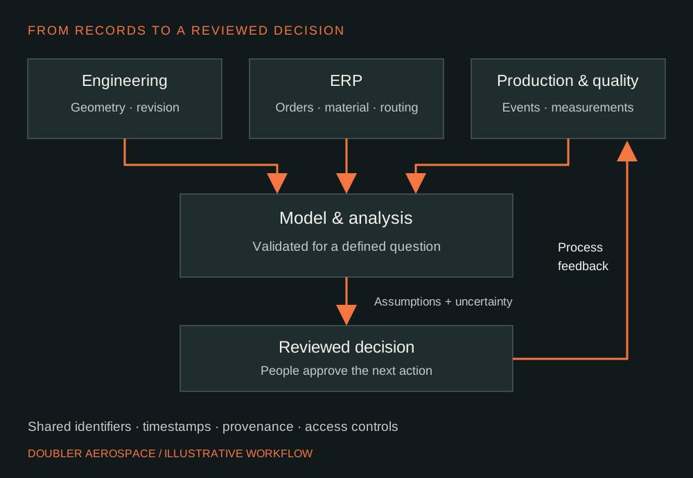
A part number alone may be insufficient. A useful join may also need the design revision, work order, serial or batch identifier, operation, and event time. Write down how corrections are recorded. If a measurement is attached to the wrong revision, a more sophisticated model can still produce a misleading answer.
4. Example: predicting a bracket batch’s completion
Hypothetical planning example, not a Doubler client case study. Consider a supplier producing machined brackets that pass through milling, deburring, and inspection. The team wants to decide which jobs to release next without overloading inspection.
Begin with a model of those three operations. Use actual start and finish records to estimate processing times, and separately record waiting, rework, and quality holds. Connect the work order to the correct routing and revision. Compare the model’s predicted completion times with completed jobs before using it to recommend a release sequence.
Then test a small set of alternatives: release the next batch now, split it into smaller batches, or wait until inspection capacity is available. Report the assumptions alongside the forecast, including staffing availability and whether a machine outage is represented. Let the planner see how the recommendation changes when an assumption changes.
The pilot succeeds only if it helps the agreed decision. Track forecast error, time spent preparing the daily plan, and the frequency of unexpected queue growth. If the records are too incomplete to explain what happened yesterday, improve event capture first. A clean operational dashboard may be the appropriate initial deliverable.
5. Test trust, uncertainty and access
NIST’s research on credibility argues that verification, validation, and uncertainty quantification should be considered throughout a digital twin’s life. In practical terms, check that the implementation works as intended, that it represents the relevant behaviour adequately, and that users understand the uncertainty of its results. [4]
For the bracket example, reserve completed jobs that were not used to tune the model, then compare predictions with their outcomes. Examine difficult cases as well as typical ones. A model that performs well during stable production may fail during a queue surge or staffing change. Define when it must stop making a recommendation and request review.
Record the version of the model, the input snapshot, and the assumptions behind each decision. Assign someone to investigate drift and approve changes. Treat a new routing or process change as a reason to reassess applicability. A validated scheduling model provides no automatic basis for accepting a part’s structural performance or conformity.
Security belongs in the design too. NIST IR 8356 discusses cybersecurity and trust challenges for digital twin technology. For a first manufacturing pilot, we recommend limited access to the required records, separate permissions for changing the model, and a review step before recommendations affect production. If any connection can issue commands, document that authority explicitly. [5]
6. A practical starting plan for aerospace suppliers
NIST’s July 2026 workshop summary identifies interoperability, credibility, cybersecurity, and workforce readiness as continuing challenges. Those findings support taking implementation and ownership seriously alongside the model itself. [6]
The sequence below is our proposed project approach. Its timing depends on data availability and scope; it is not a promised deployment schedule.
- Choose the decision. Name the user, the recurring question, and the action the output should support. Write a measurable baseline.
- Audit a small sample. Follow several work orders from engineering release to completion. Identify missing identifiers, conflicting revisions, and undocumented holds.
- Build the narrowest useful connection. Link only the records the decision requires. Show missing or stale inputs clearly, and preserve the original source records.
- Run alongside the existing process. Compare recommendations with actual results. Keep a log of discrepancies and the reasons operators or planners disagree.
- Agree the operating limits. Define acceptance criteria, the owner, review triggers, and a fallback when the model or data feed is unavailable.
- Expand only after evidence. Add another operation or data source when the pilot’s results justify the cost of maintaining it.
Where to begin at your facility
For many teams, the first useful work is agreeing on part identifiers, revision rules, routing records, and inspection handoffs. That work makes subsequent analysis easier to assess and gives people a clearer picture of production even before a predictive model is introduced.
Doubler Aerospace’s CAD workflow services and ERP development services can be scoped around those foundations. Bring a workflow that is creating delays or duplicate entry, and we can discuss an appropriate first step.
Connect the workflow behind the hardware.
Tell us which engineering or production handoff is slowing your team down.
Discuss your workflowReferences
Primary sources reviewed 30 September 2026. Practical recommendations and the bracket example are Doubler Aerospace’s editorial synthesis.
- NASA Biological & Physical Sciences Division. Why does the world (and NASA) need digital twins? Updated 18 February 2025.
- Shao, G. Use Case Scenarios for Digital Twin Implementation Based on ISO 23247. NIST AMS 400-2, 2021. DOI: 10.6028/NIST.AMS.400-2.
- NASA. JSTAR Digital Twins. Updated 19 May 2026.
- Shao, G., Hightower, J., and Schindel, W. Credibility consideration for digital twins in manufacturing. Manufacturing Letters; NIST publication record, 16 December 2022.
- Voas, J., Mell, P., Laplante, P., and Piroumian, V. Security and Trust Considerations for Digital Twin Technology. NIST IR 8356, 2025.
- Frechette, S., Shao, G., and Pease, M. Digital Twins Workshops Summary Report. NIST IR 8620, 21 July 2026. DOI: 10.6028/NIST.IR.8620.